|
In situ NiMH battery charging circuit
In my geiger counter project I used a PCB solderable rechargeable NiMH battery (so no replacing possible).
Unfortunately, I didn't really wire it properly. I figured I'd just connect the 4.8V NiMH battery to a 5V voltage
and let nature take its course. Not quite so. NiMH requires one to force current into the battery so my "solution"
there didn't really do anything.
One has to take this into account:
- To get any charging speed you need to push lots of current through, in general for that you need a high voltage source/high current source.
- In case you overcharge, the battery can overheat, cause a fire and burn down your house. Ouch.
- If the battery is connected to a circuit (a working one), you don't want to fry it with the high voltage.
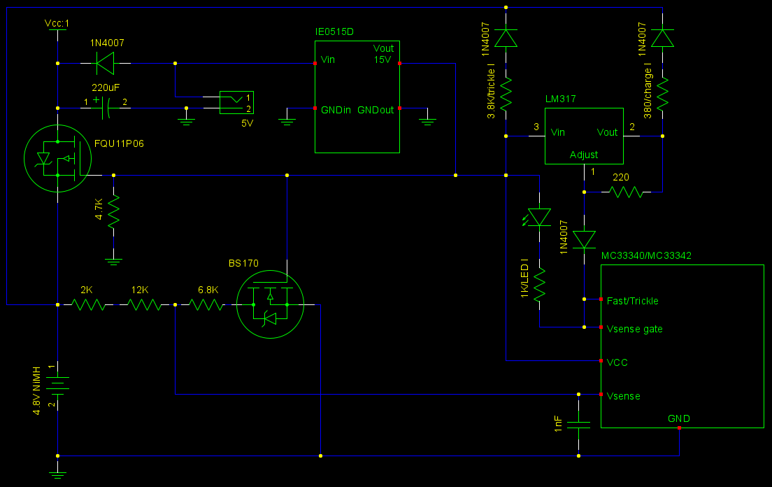
So here's my solution.
- Use a charge pump/voltage converter to get high voltage (the one I use here is quite expensive though).
- Use MC33340/MC33342 battery charge controller. This monitors the battery voltage and turns the charging off. It also implements the delta-V charge completion detection. That is at the end of the charge cycle the battery will start to lose voltage. The IC detects this and terminates charging.
- Isolate the circuit from the battery with a p-channel MOSFET (low internal resistance) to prevent high voltage damage.
Using the special battery charging IC makes things easier. One could naturally have their own MCU run this show but it's not that trivial. Aside from comparing battery voltage to a reference, the NiMH charge characteristic also involves voltage drop detection - an indicator that full charge has been achieved. And I didn't want to overly modify my existing circuit. Rewiring/reprogramming MCU-s is a pain.
Other comments about the circuit.
- Run circuit while battery is charging (the diode from the 5V voltage source into the Vcc provides current).
- Trickle charge, around 2-3mA (from (15V-1V-4V)/3800=2.6mA).
- Charging current is (15V-1V-4V)/380Ohm=26mA.
- Ground pins of IE0515D are connected together, so I don't use the isolation feature of this component.
- The BS170 isolates the voltage detection circuit. So there is no drain on the battery once the charger is off.
- The 220uF capacitor at output is there to prevent turnoff when the charger is plugged off - give time for the mosfet to turn back on. Could be it is not working as intended - one slight flaw in this circuit - could reset the circuit for a moment the wall power is turned off. In that case one could reduce the 4.7K pull-down resistor to deplete the +15V faster.
- LM317 is basically operated here as an on-off switch. The LED turns on when the battery is full. When charging it blinks every 1.3 seconds.
- Pulls 120mA from a 5V source.
- Voltage divider (14K, 6.8K) has been selected to terminate charging once battery hits 6V (divider output goes over 2.0V).
- The 1nF between Vsense and GND is for stability.
- The 4.8V NiMH battery contains 4 cells. At charge end each of them is around/below 1.5V, so at total 4*1.5=6V.
- At battery's 6V the Vsense sees 6*6.8/(6.8+14)=1.96V (see voltage divider).
Disclaimer: I'm not an EE. If this circuit burns down your house, don't blame me. Use at your own risk.
|