I found some cheap Russian made Geiger-Müller tubes on eBay and decided to get one.
This page is about my efforts trying to build a simple radiation detector.
This time I decided to do something adventurous and use an unconventional power source.
I bought a cheap wind-up lamp and extracted the dynamo-gearing-handle mechanism from it.
It's difficult to build one on your own and why not use what is available.
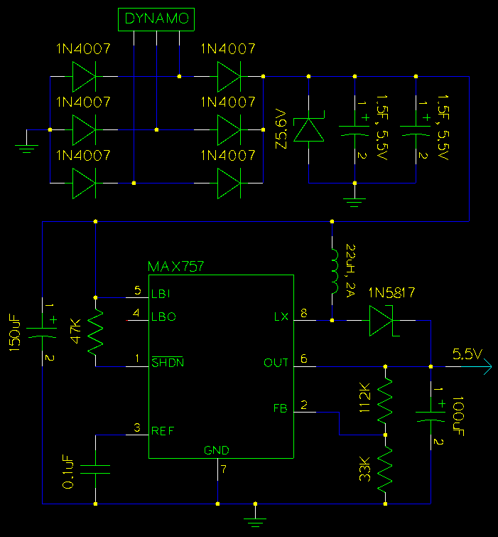
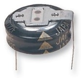
Instead of batteries I'm going to use a supercapacitor. I got a couple of Panasonic's
1.5F/5.5V battery backups caps.
To get a stable reference voltage I'm going to use the MAX757 switching regulator.
It's going to pump the voltage up to stable 5.5V.
The schematic is following:
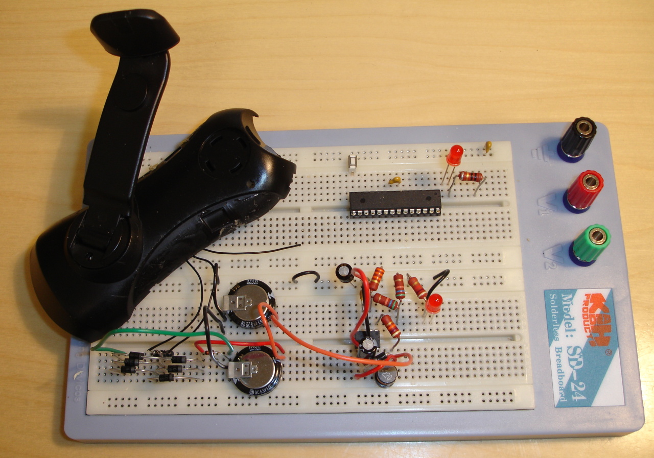
And here is the completed circuit powering a LED:
The caps don't like to take much current when the voltage goes higher, so winding up to 4V is probably
going to be the maximum and is going to take a minute. If I use 2 capacitors I'll get 3*4^2/2=24 Joules
of energy into the caps. The regulator works down to 0.8V and around 80% efficiency, so that gives us 18J of usable energy.
At 5.5V output and 10mA draw this is going to last for 18/(5.5*0.01)=327 seconds or at least 5 minutes.
Sounds good enough to me. This of course only if I manage to build the rest of the circuit to draw
that little current. We'll see.
Warning: high voltage can be dangerous to your health. If you don't know what you're doing, then don't do it.
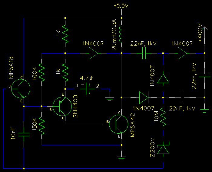
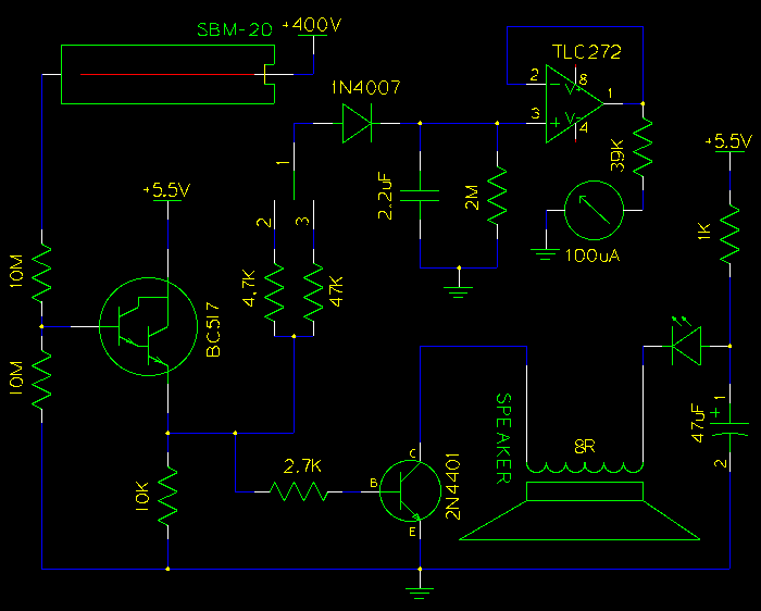
The Geiger-Müller tube requires high voltage to function. To get this we need to use another special circuit.
This circuit is mostly stolen off techlib's Geiger counter page.
To be perfectly honest I don't fully understand how it works, however I do get very low current usage with this circuit.
Basically it's a charge pump, with a voltage doubler. Voltage is regulated by the Zener diode(s) (you can use many in series to achieve the desired voltage exactly). As the current
it provides is very small, measuring it using a regular 1MOhm multimeter is not possible. Instead one has to use a
1GOhm resistor in series with the multimeter probe - this causes a reduction in the displayed voltage by a factor of 1000.
My multimeter shows 402mV. The inductor is of low resistance.
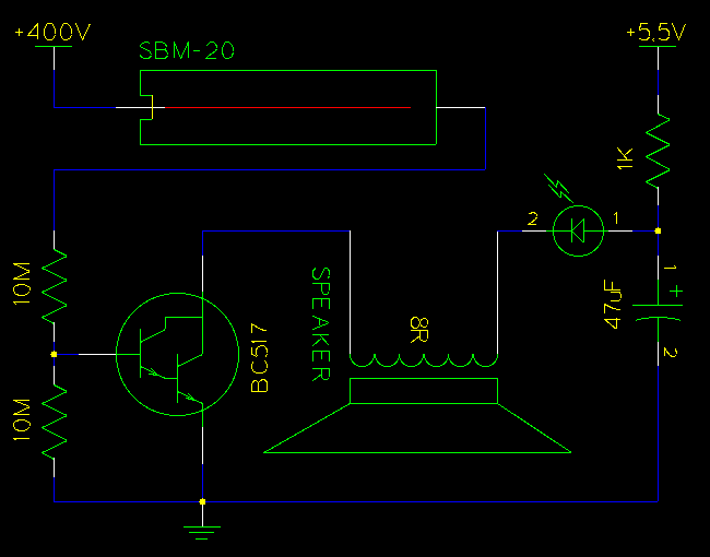
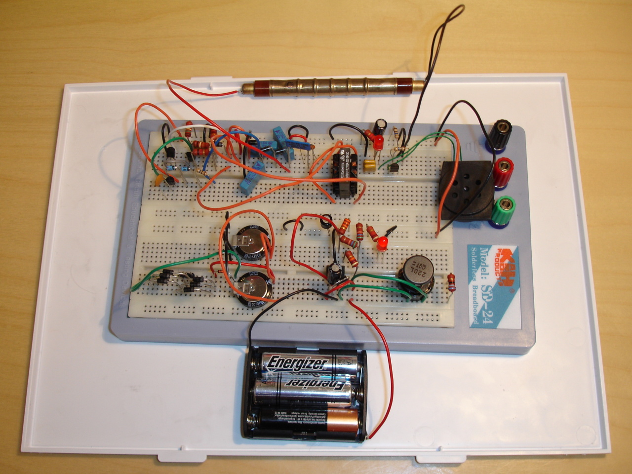
This is the simplest output for the detector I could figure on my own. This should flash a LED and also produce a clicking sound.
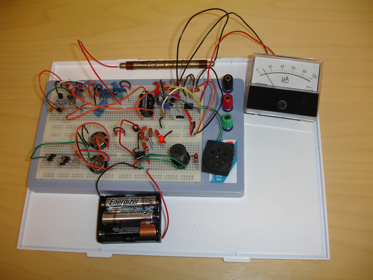
This circuit seems to work. I get some 20 clicks per minute. This should account for the background. However, I don't yet have anything radioactive around so could be this is just some EM interference/malfunction. I need a source to test it with. Note that I'm using a 3xAA 4.5V power source as winding up all the time for testing got quite annoying ;)
The geiger tube I use here is a Russian made SBM-20 (СБМ-20). I got it off eBay from Ukraine and it's probably 30 years old.
What I need now are some radioactive samples to test against. And try to reach and see what happens at saturation. Will check local stuff first. May have to buy some uraninite or other similar rocks off eBay.
Here's a video of the circuit working on some dictyonema shale (Graptolitic Argillite). This stone is exposed to the ground in this area and is responsible for most of the radon gas leaching into dwellings. It contains uranium, thorium, molybdenium, vanadium and other elements. The dial moves up to 20 in the background. With the tube on top of the shale the dial goes up to 40. This kind of slight increase was to be expected as the shale is only mildly radioactive.
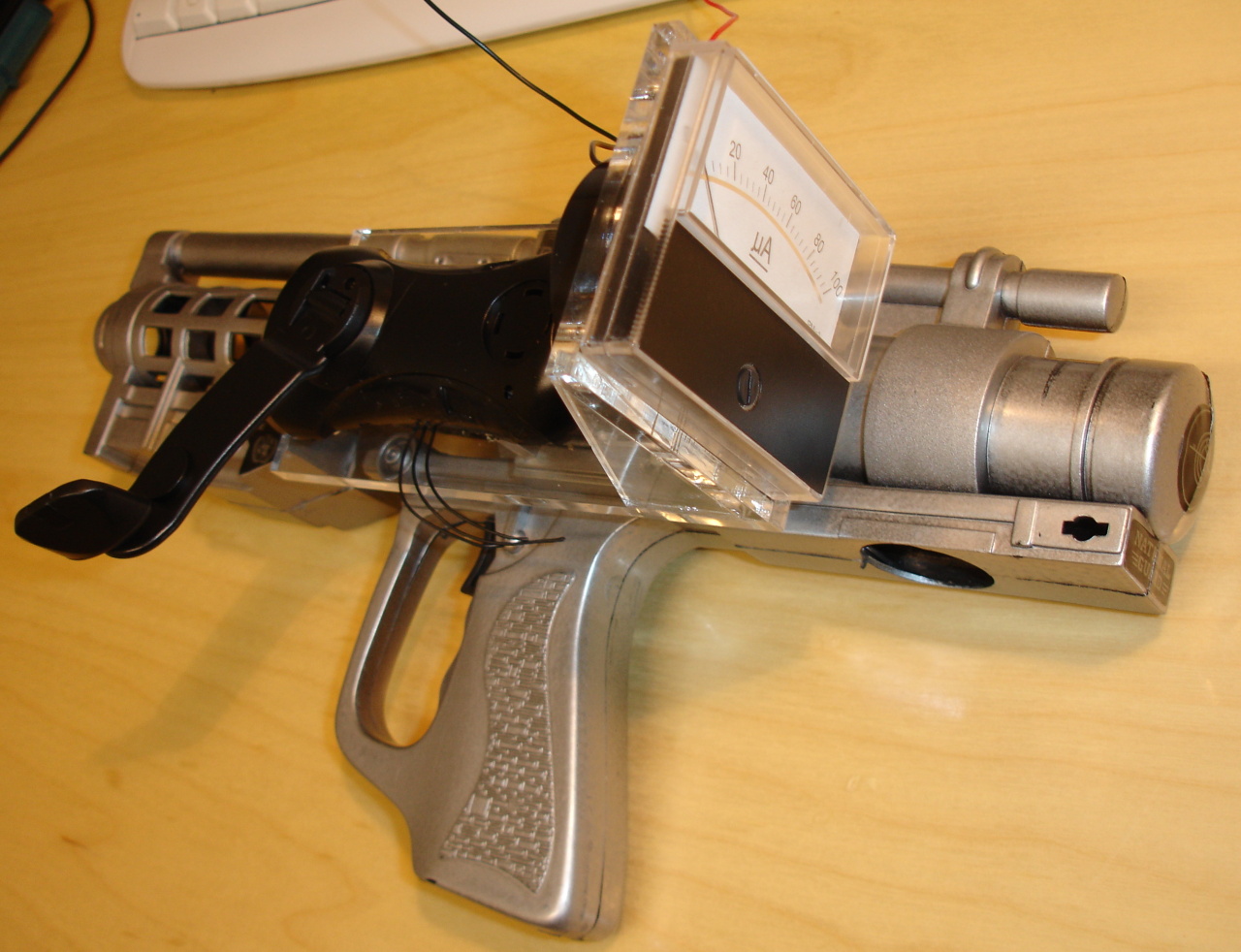
Time to a pick a suitable package for the circuit. At the moment I'm going with a toy gun design.
I had some pieces of clear acrylic laser-cut to size (to design drawn using the Solid Edge 2D CAD), glued them together,
attached the wind-up generator and the analog meter. The gun came with its own speaker and a trigger mechanism,
can make direct use of those. Looking good :)
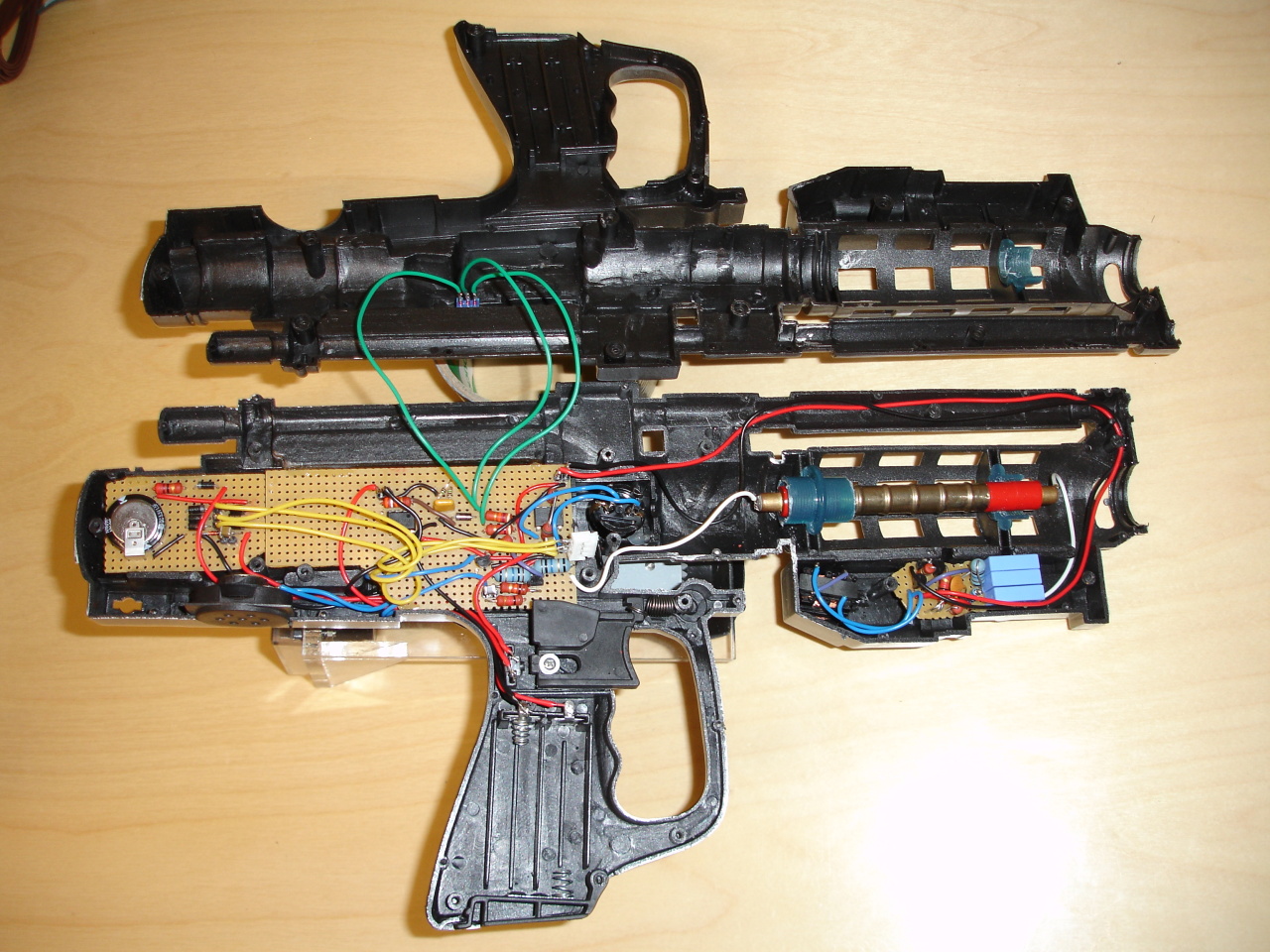
This is with all the components soldered onto a circuitboard and placed into the gun. The wires to the far
side are for the ON-ON tumbler that sets the meter resolution. There is a battery compartment - I rigged it
so that if batteries are placed in they work as a backup. The gun's trigger mechanism turns the geiger
counter on. For ten seconds of winding I got several minutes worth of operation, or more precisely it kept
on working and I got tired - excellent performance.
I decided to build another one. This one will be with a digital readout
and only one button. Press once to turn on. Press again to turn on in mode 2.
Hold down for two seconds to turn off.
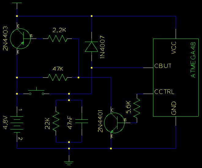
As mechanical multi-switches are not available, I decided to go with a transistor
switch based design.
Here I use a MCU to run the show. Pressing the switch will allow current to flow into the
circuit through a diode, powering up the MCU. The voltage might be slightly lower than stock
due to diode voltage drop but it is enough to turn the circuit on. Once the MCU is on - it sets the CCTRL to high and so
power is channeled through the PNP transistor instead of the button. We can
release the button now - circuit keeps on working - as long as the MCU keeps the
CCTRL high. Thanks to the diode the MCU can also detect when the user presses
the button down. Maybe there's a simpler way to do it - however this design
seems to work just fine for me. At turn-off position the circuit seems to take less
than 1uA of current (my meter shows 0).
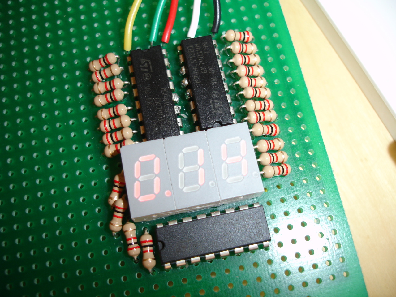
Next item on the list is the digital readout. I'm using three 8-segment (7+1 for dot)
LED modules. They are a pain. I cascaded three 74HC595 serial to parallel converters
together. This means I need only 3 control leads connected to the MCU - so I can
bitbang them. And 24 resistors. And an insane amount of wire to make the connections.
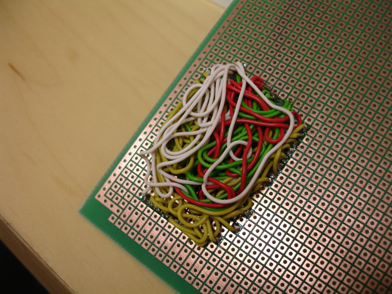
It looks kind of good from this side:
But on the other side it's a real crow's nest. I mean look at it. Even lord Yog-Soggoth would be
proud of this. It is bound to strike fear in the hearts of a common man. Not from a thing by itself,
but by one starting to think of the mind who was behind the design and construction of it.
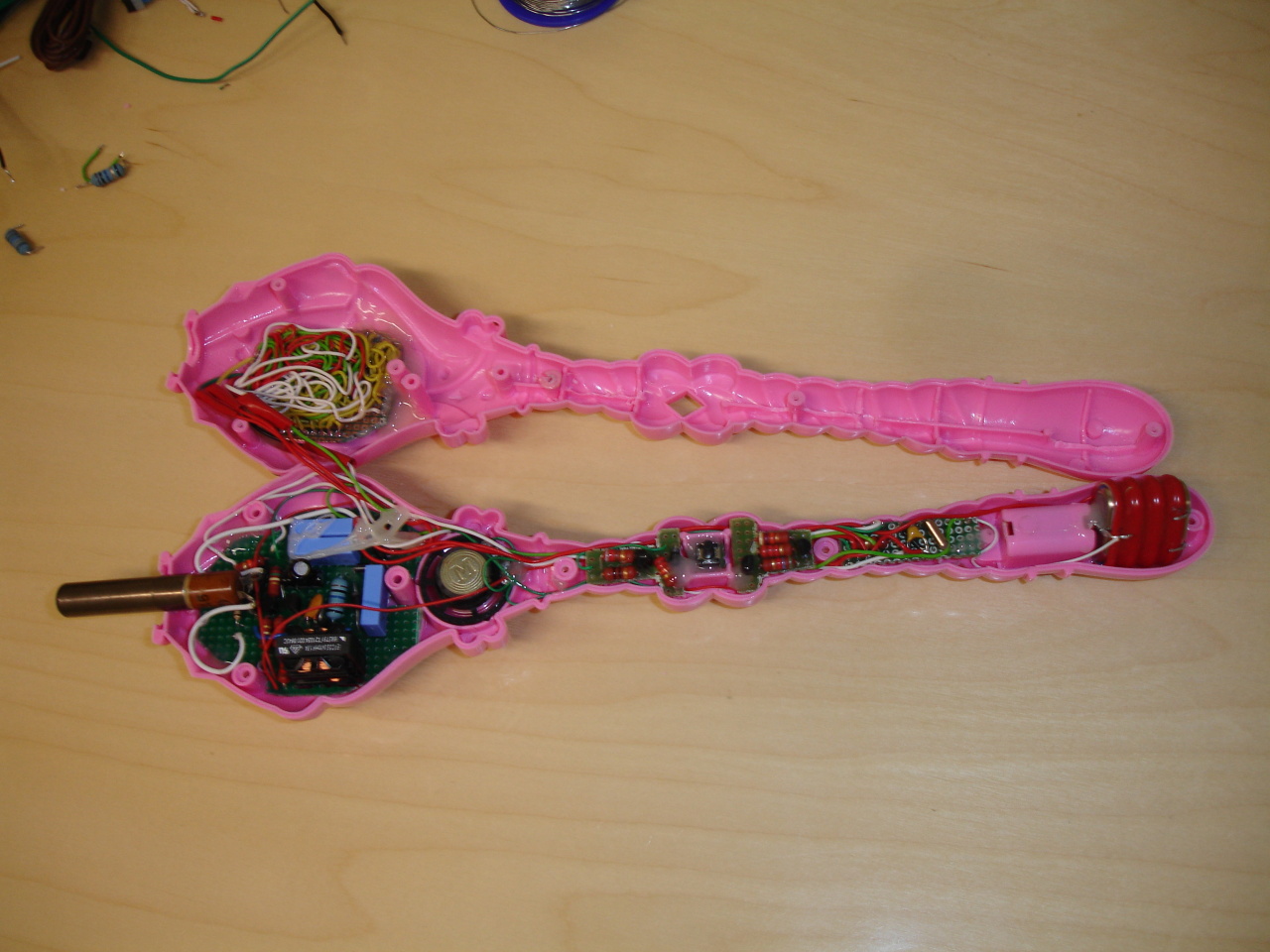
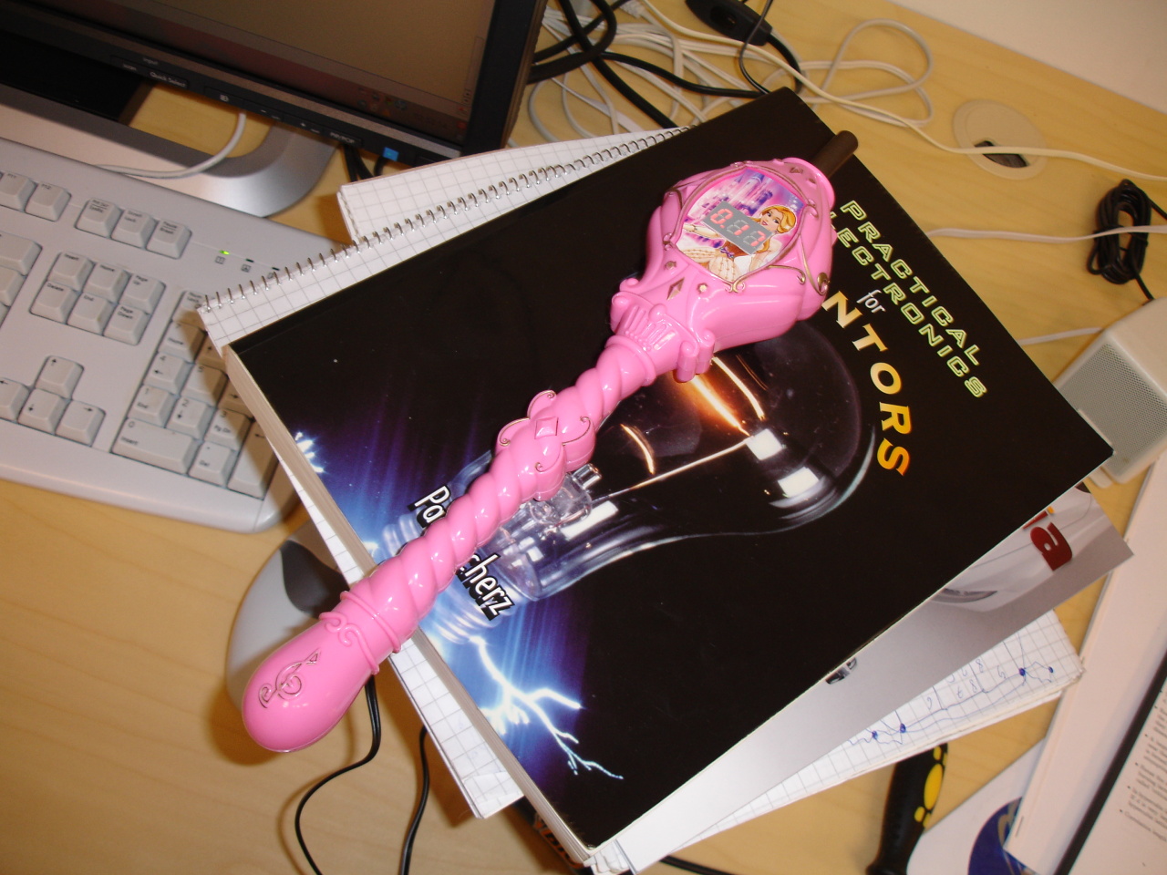
While I was shopping for toys, I found this wonderful package. It was a pink girly magic princess wand. It has
a ON-OFF button, a blinking LED and and a small speaker within it. And it plays goofy music.
This is what it looks with all the geiger counter electronics inside. For this one I used a different russian
geiger tube, CI-29BG. It's smaller and fits inside my wand.
I replace the simple mechanical ON-OFF button with my transistors based ON-ON-OFF switch. It works in two modes -
simply counting clicks and then clicks per second, averaged over 3 minute timespan.
It is powered by a 5V wall charger. There is also a small 120mAh NiMH 4.8V battery inside. But the charging is very slow as
I didn't really know what I was doing. I hope it will provide about one hour of worktime before charging is needed again.
The device consumes about 30mA of current while operating. Around 25mA of that goes for powering the LED display.
I finally got a clue and bought a regular smoke detector. Not the optical variation but one using "ionization technology". It has americium 241 that emits ionizing alpha radiation. There is also
a weak component of gamma emissions present and it seems my detector can easily pick these up.
The only thing is that the detector has to be close enough to the radiation source. For that I needed to strip the smoke detector
and expose the disk that has the americium in it. NB! Alpha emitters can be hazardous to your health if you ingest or breathe it in.
It can enter your metabolism that way and cause cancer. So don't go randomly destroying smoke detectors.
Here's a picture of the radiation source:
I also made a little demonstration video of my magic wand geiger counter:

 Instead of batteries I'm going to use a supercapacitor. I got a couple of Panasonic's
1.5F/5.5V battery backups caps.
Instead of batteries I'm going to use a supercapacitor. I got a couple of Panasonic's
1.5F/5.5V battery backups caps.