The aim of my new project is to work with flash cards to do data storage (and retrieval) and also to get a handle on A/D and D/A converters. The natural application for that is sound.
In various microcontroller related applications the data storage is
very important. The easiest would be to use a standard ready-made
solid state storage solution.
The MMC (Multi-Media Card) and the SD card provide those.
It is possible to interface with the MMC and the SD cards using
SPI - serial peripheral interface. SPI is a full duplex three-wire
synchronous data transfer mechanism. SPI is supported by the AVR
chipset and is also used internally by the AVR family for the ISP (In-system Serial Programming).
The cards that are supported are the MMC, the SD and the next generated SDHC (4GB+ cards).
SD cards usually use a FAT file system. Depending on card size either FAT16 or FAT32. The SPI interface allows direct block by block read and write access. The FAT filesystem layer has to be added additionally in the software level.
Most of the work has already been done by various amateurs on the Internet with source codes freely available:
The code size for a simple application that reads and writes a file was at 8KB. This is quite a bit and so only chips with larger programmable flashes can be used (ATMega168 has 16KB). The TinyFAT requires a 512 byte memory buffer so ATMega168 with its 1KB is sufficient again.
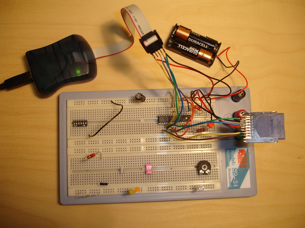
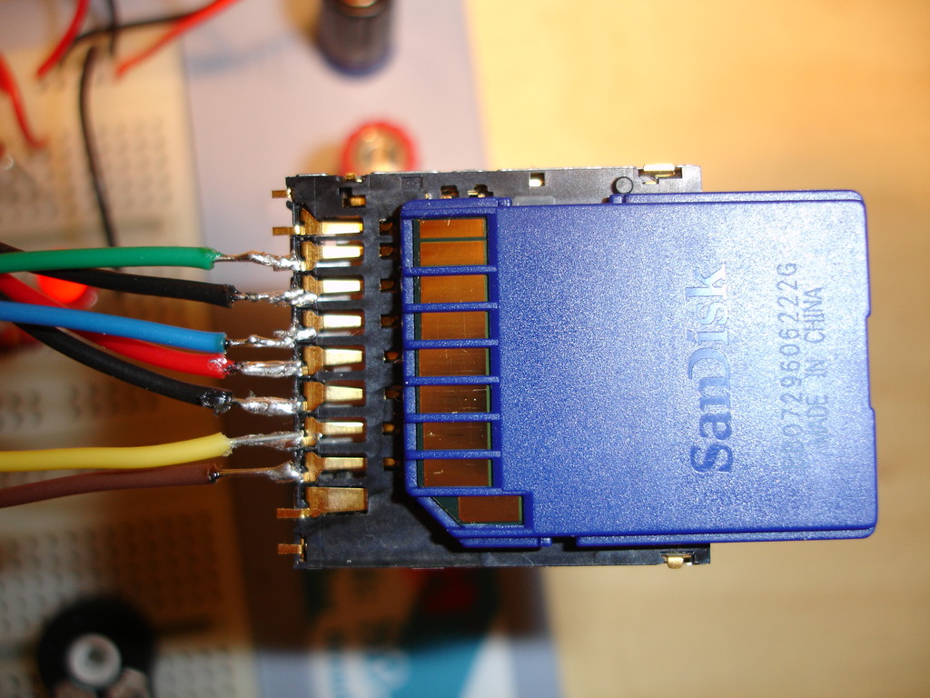
This picture shows my setup. I have both the ISP and the SD card directly connected to the MCU. As I use a double AA battery set, the voltage is at 3V and so no voltage manipulation is needed (SD cards work at 2.7-3.6V).
The pins from the bottom up for this SD card are:
#
Color
SD function
Connected to
9
-
DAT2
-
1
BROWN
DAT3/CS
SS
2
YELLOW
CMD/DI
MOSI
3
BLACK
Vss1
GND
4
RED
Vss
+Vcc
5
BLUE
CLK
SCK
6
BLACK
Vss2
GND
7
GREEN
DAT0/DO
MISO
8
-
DAT1
-
Everything worked perfectly with my smaller 1GB regular SD card. I did run into a bit of trouble with my bigger 4GB SDHC card. It turned out later on that my batteries were almost dead and so the bigger SDHC card refused to respond. Also I had to explicitly enable the FAT32 support in the TinyFAT implementation.
The next order of business is to attach an electret microphone to one of the A/D converters of our Atmega168 chip.
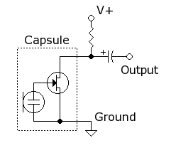
The picture to the right (taken off wikipedia) shows a typical electret microphone configuration. What I found is that the resistor size controls the DC component. Increasing it lowers the signal level.
The ATMEL/AVR ADC converters do 10 bit conversion - and so give a number between 0 and 1024 measuring the voltage level between AREF and GND pins - so there are no negative values. Alternatively one can instruct the AVR to use Vcc/AVcc instead of the AREF. As the ADC works on DC there is no need for the capacitor - the capacitor would remove the DC and give us AC.
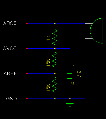
It is in our interest to calibrate the signal DC component so that the average voltage would be in the middle between GND and AREF. This can be done using the resistor. What I found is that the signal amplitude was about the same at different DC levels. That means decreasing the AREF-GND voltage while increasing the resistor value will give us better resolution. The reference voltage can be provided by the means of a voltage divider.
This is my current configuration - a voltage divider to halve the reference voltage - from 3V to 1.5V. The 14K resistor value was not the result of a calcluation but from trial and error.
The ADC converter seems to work fine. There is some noise still in here but I'll wait until I get my oscilloscope before I start trouble-shooting that.
Once we get the ADC converter running we need to decide at what frequency to sample the signal. The ADC converter on the ATMEGA168 works best at 50-200kHz frequency (we can divide the main clock frequency to get down here). A single conversion in free running mode takes 13.5 ADC cycles. At 200kHz this gives us the maximum sampling rate of 14kHz.
The CD quality is at 44kHz, a person speaking can be understood at 2-4kHz. Most phone systems support 8kHz. As we are limited by the frequency anyways I'll aim for the 8kHz range.
There is one more limitation - data storage bandwidth. At 8kHz and 16 bit sampling we generate 16000 bytes per second. This might not seem a lot and it isn't. For one we can do 8 bit storage per sample - this is acceptable quality. There is a problem though. Our ATMEGA168 only has 1kB of RAM, half of which is already consumed by the TinyFAT implementation. We can't do efficient buffering because the writes to the SD card already work at 512 byte chunks. Also it seems the TinyFAT can't do streaming writes. The end result is that we might have to do direct streaming writes into the SD card - discarding the filesystem and interfacing with a PC (the card can still be read directly on a PC using special tools/software). I need to do some SD card benchmarking to get to the bottom of this.
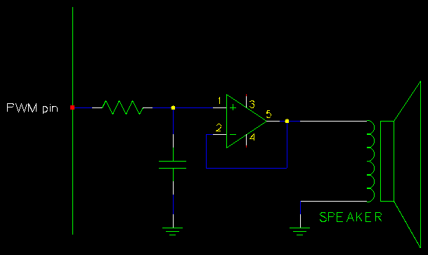
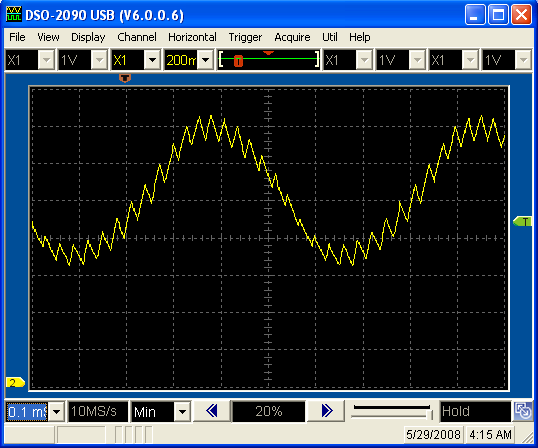
One very simple way to build a DAC (digital-analog converter) is to use PWM, send it to a low pass RC filter and so get an audio signal.
This "1-bit DAC" design is described on this fpga4fun page. Basically we send pulses down a pin at high frequency. The low pass RC filter erases the high frequency resulting in a more proper signal (signal level depends on the low-high ratio of the pulses). To resolve the impedance problem the signal is sent to an opamp that is set to work in unit gain buffer mode.
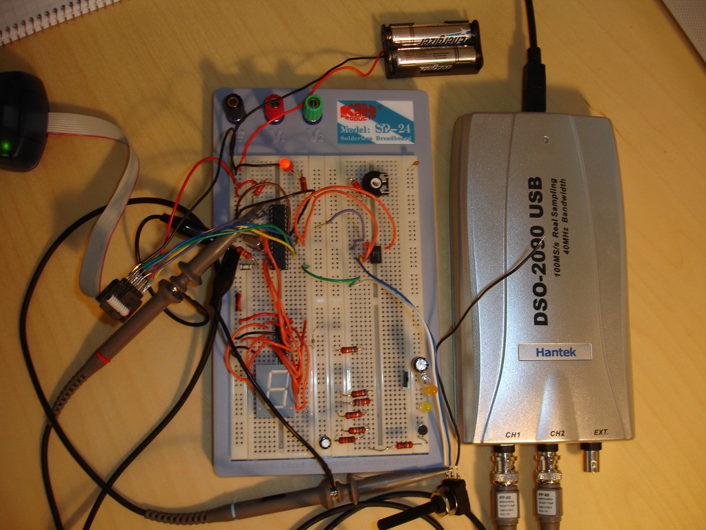
This gives me an opportunity to try out my brand new 2-channel digital/USB oscilloscope.
Unfortunately the PWM requires high clock frequency on the MCU part which rules it out for my design. Also to get a proper signal for my low impedance (8R) speaker it has to go through an opamp. But as I use low voltage (3V) I need a low voltage opamp which I don't have at the moment.
Getting proper audio turned out to be more difficult than I anticipated. As I'm
using low voltage battery power most "standard" chipsets out there don't work
very well. I ended up using 4 AAA batteries and in stacked configuration giving
me three leads: GROUND, +3V and +6V.
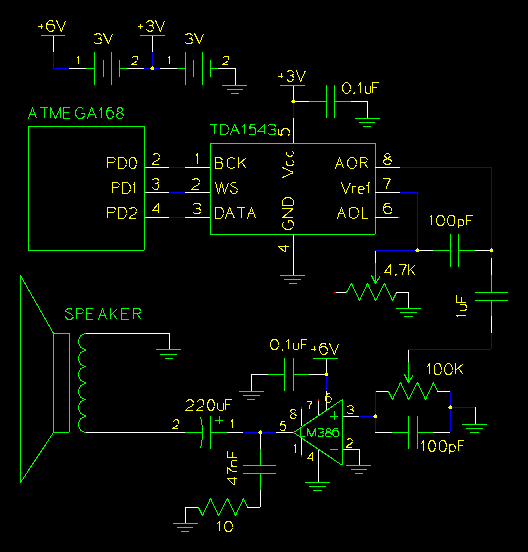
The first stage is the digital-analog conversion (DAC). For that I use the TDA1543 chip.
It's a 16 bit dual channel (stereo) DAC. I only use one channel and at 3V I got
it to give me about 9 bits of effective DAC. This chip uses
I2S for communication (3 wire, one-to-one communication protocol). As AVR does not natively
support I2S I had to emulate it using simple pin programming. At 10MHz
MCU speed I can update one channel at about 60KHz. The 4.7K trimmer
attached to the Vref of the DAC is essential in configuring it to work
in the given bit range.
Once the signal is generated at the DAC I remove the DC component
and send it on into the LM386 audio opamp. LM386 works with single
supply (only ground and +6V) but its output is biased to the
middle of the supply voltage. So the input is an AC signal and the
output is DC fluctuating around the middle of the given supply voltage
range (so for +6V that makes it at +3V).
The LM386 amplification is set at 20 in this configuration, so
I also have a potentiometer between the DAC and the opamp to allow
for volume control. Additionally you can see two 100pF capacitors
placed at the DAC and at the opamp. These are essential at removing
noise and making this quite flaky circuit working.
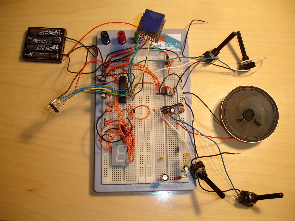
This picture shows my setup that plays music off an SD card. The music is stored
as 8 bit samples. Getting the music into the SD card was quite easy (NOTE: be careful with the dd command, you can easily destroy the filesystem of your hard drive and lose all your data if you overwrite the wrong device):
There is one problem with the batteries: their voltage drops as they drain. This drop can be significant (down to 1.3-1.4V from the stock 1.5V) and affects our circuit in following ways: the TDA1543 is rated at minimum 3.0V, with the two batteries dropping the voltage can go down to 2.6-2.7V. The tuning resistor needs to be retuned at that kind of change as well - not a practical option.
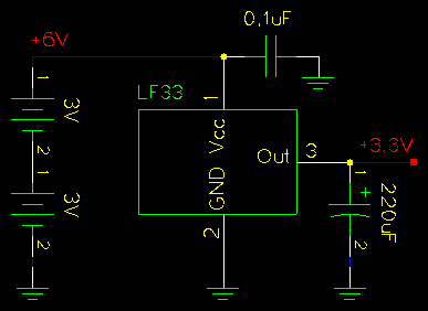
What is the solution? To use the 6V we get from the 4 AAA batteries and somehow downgrade it to the correct voltage and do it in a way that does not depend on the drop in the input voltage. There are two main types of components that can be used for that: a voltage regulator or a switching regulator. Voltage regulators are cheaper but their problem is that they waste power. If we convert from 6V to 3V then we'll use double the normal power - it is wasted as heat.
Still a voltage regulator is an easy solution for my project - and most of the power anyways goes to driving the speaker - the IC-s don't take that much. So I've settled to using the LF33. It converts my 6V down to 3.3V.
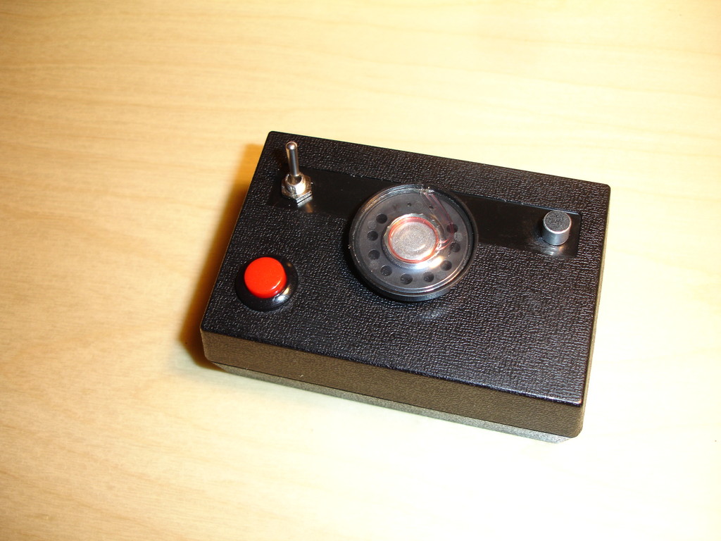
The tumbler is the on-off switch. The red is the record button. In the middle is the speaker. And on the top right is the microphone.
I've grown quite weary and tired of this project so I never got to working out the
noise issues. Also the ADC I get is effectively only 7 bits - I could have easily
done much better. Most of the noise I believe comes from two sources:
the SD card which can be heard as regular blips (each time a 512byte block
is read or written) and the LM386 opamp which is not quite perfectly stable
at this low voltage.
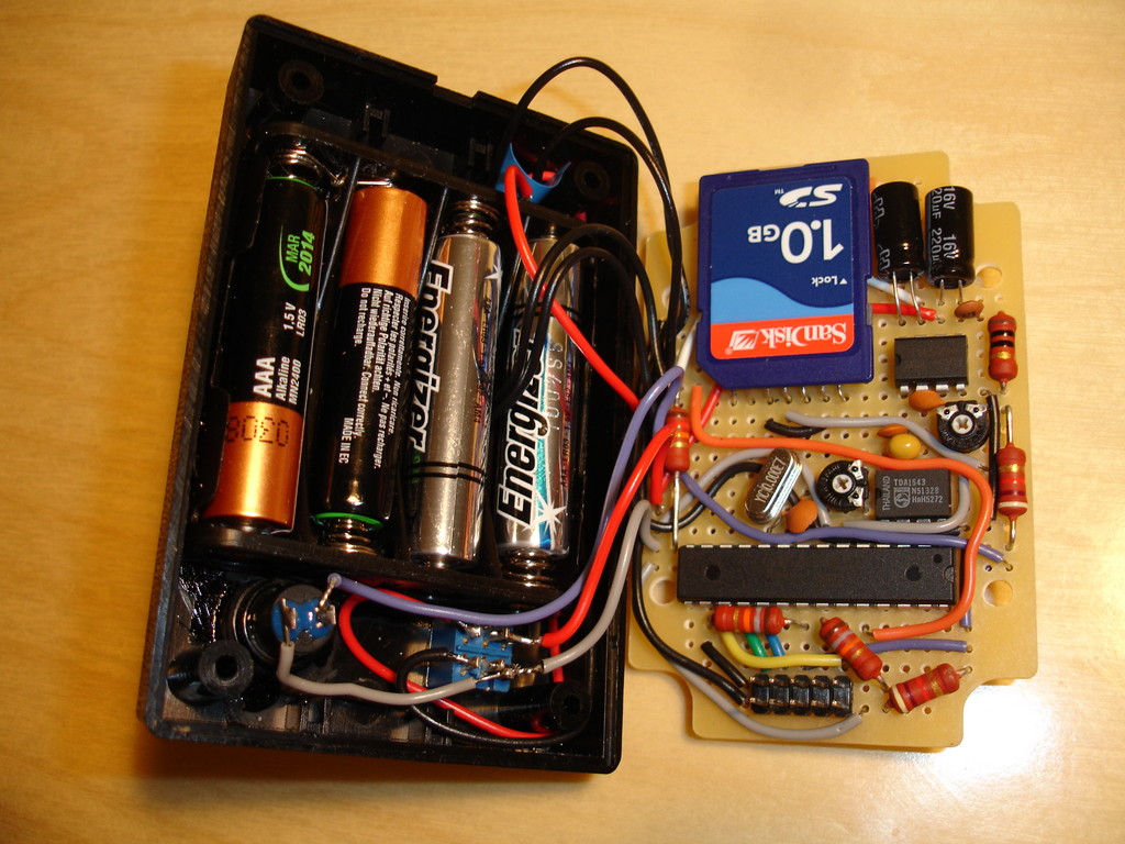
As a good tradition I put the circuit again into a neat box. Here are the insides:
The SD card holder I had broke down so I soldered it directly on. This pictures is still missing
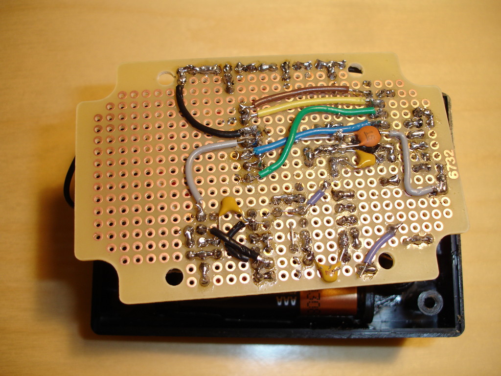
the voltage regulator though. And here's the backside:
 This is my current configuration - a voltage divider to halve the reference voltage - from 3V to 1.5V. The 14K resistor value was not the result of a calcluation but from trial and error.
 There is one more limitation - data storage bandwidth. At 8kHz and 16 bit sampling we generate 16000 bytes per second. This might not seem a lot and it isn't. For one we can do 8 bit storage per sample - this is acceptable quality. There is a problem though. Our ATMEGA168 only has 1kB of RAM, half of which is already consumed by the TinyFAT implementation. We can't do efficient buffering because the writes to the SD card already work at 512 byte chunks. Also it seems the TinyFAT can't do streaming writes. The end result is that we might have to do direct streaming writes into the SD card - discarding the filesystem and interfacing with a PC (the card can still be read directly on a PC using special tools/software). I need to do some SD card benchmarking to get to the bottom of this.
 There is one problem with the batteries: their voltage drops as they drain. This drop can be significant (down to 1.3-1.4V from the stock 1.5V) and affects our circuit in following ways: the TDA1543 is rated at minimum 3.0V, with the two batteries dropping the voltage can go down to 2.6-2.7V. The tuning resistor needs to be retuned at that kind of change as well - not a practical option.