|
Interfacing with a computer, self-programming
The aim of this project is to work on interfacing with a computer - that is to allow communication between a regular personal computer (laptop/desktop) and an AVR microcontroller.
The easiest way to interface is to use the serial protocol RS-232. RS-232 was developed in the 1960s for communication between mainframes and their peripherals and so is quite antiquated, but it is very simple and easy to use.
Modern computers unfortunately no longer come with the serial port. USB has pretty much completely taken over when it comes to attaching devices to our computers. Additionally USB is a lot more complicated to use than RS-232. But there are simple USB-serial converters. I got myself a cheap PL2303 chipset based converter:
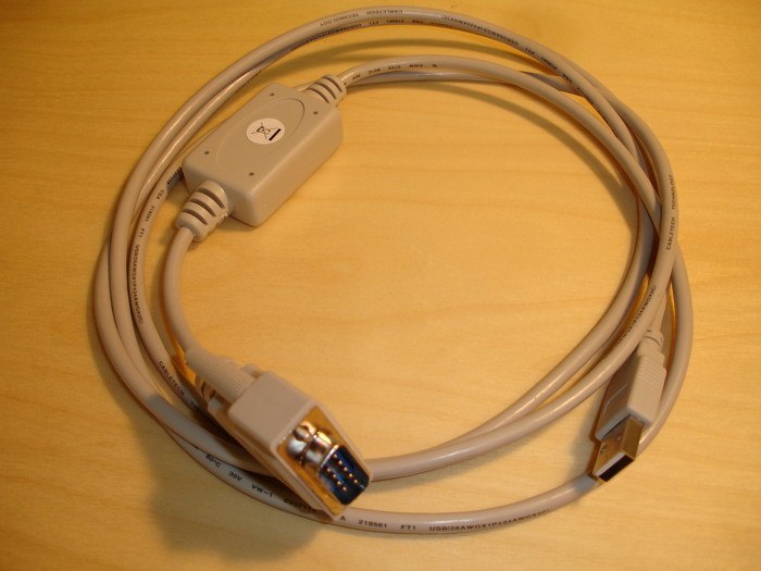
When I plug it into the USB port this is what I see at dmesg:
usb 3-2: new full speed USB device using uhci_hcd and address 4
usb 3-2: new device found, idVendor=067b, idProduct=2303
usb 3-2: new device strings: Mfr=1, Product=2, SerialNumber=0
usb 3-2: Product: USB-Serial Controller
usb 3-2: Manufacturer: Prolific Technology Inc.
usb 3-2: configuration #1 chosen from 1 choice
pl2303 3-2:1.0: pl2303 converter detected
usb 3-2: pl2303 converter now attached to ttyUSB1
My Linux kernel connects the serial line to /dev/ttyUSB1, with following default settings: speed 9600bps, no parity, 8 data bits, 1 stop bit. From user level application perspective this is like a regular serial (COM) port device.
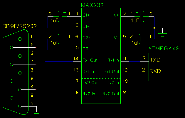
How to connect the serial port to the AVR? This can be done using the USART (universal synchronous/asyncronous receiver/transmitter) functionality the AVR family usually incorporates. UART is logic wise pretty much compatible with the RS-232 with the exception of used voltages. RS-232 uses high voltages (up to +3V..+25V and -3V..-25V) and so is not directly compatible with our AVR MCU. Fortunately there is a chipset called MAX232 that uses internal charge pumps to generate the necessary high voltages on its own. The version of the chip I use works from a +4.5V single supply (3 AA batteries). This is a schematic against the ATMEGA48:
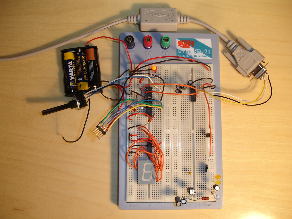
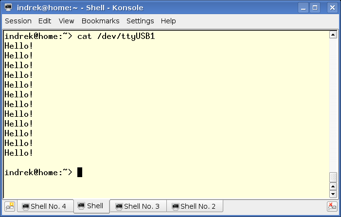
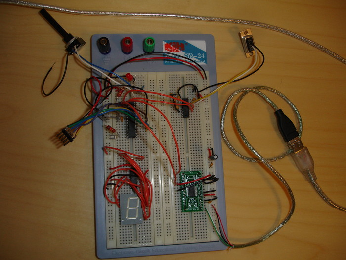
This picture shows my circuit in action sending "Hello" to the serial port:

With default parameters the port can be read even with the simple UNIX cat command. It is important to match the baud rate speeds - and that on both sides. For example the default 1MHz frequency the ATMEGA48 comes with is incompatible with 9600bps operation due to frequency division - I had to update the MCU frequency to 8MHz.
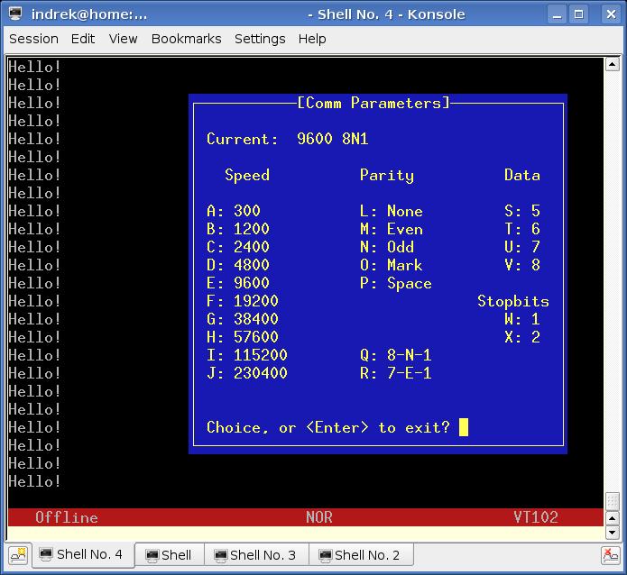
Alternatively a terminal application like minicom may be used for testing - minicom supports setting correct speed, parity and stop bit settings:
Here's the source code for sending "Hello!":
#define FREQ 8000000

static void USART0Init (uint16_t brate)
{
  UBRR0 = FREQ / 16 / brate - 1;
  // enable receive and transmit
  UCSR0B = _BV(RXEN0) | _BV(TXEN0);
  // asyncronous, no parity, 1 stop bit, 8 bit character size
  UCSR0C = _BV(UCSZ00) | _BV(UCSZ01);
}

static void USARTSend (const char *str)
{
  while (*str)
    {
      while ( ! (UCSR0A & _BV(UDRE0)) );
      UDR0 = *str++;
    }
}

int main ()
{
  USART0Init (9600);

  while(1)
    {
      for ( uint32_t i = 0; i < 50000; i++ )
          __asm__ __volatile__ ("nop");
      USARTSend ("Hello!\r\n");
    }
  return 0;
}My next task is to get my ATMEGA48 chip to self-program its flash with program
data coming over the serial line. In theory the data could come from anywhere
but the key here is to program the flash without any special hardware, be
it universal parallel programmer or the STK500mkII ISP device.
Many AVR chipsets have a separate boot section where one has to store the flash update
routines. Not so with ATMEGA48 - ATMEGA48 can be programmed from pretty much any
flash section. Still the idea is to place the update routine at the end of the flash
memory, to a place where it won't be disturbed. Overwriting the update routine
while it is executing is not a good idea. So the update routine is a static,
un-changing program code in the flash, it only updates the lower flash space with
a new program code.
For ATMEGA48 the first thing one has to do is enable the self-programming
fuse bit in the extended fuse byte:
avrdude -c avrispv2 -p m48 -P /dev/ttyUSB0 -U efuse:w:0b0:m After that the SPM command will start working.
Now we need to write the flash update routine. I've written it so that the update
function is part of the main program code but is placed in a separate special linker
section that is usually not included. The update function must be self-contained,
that is it should not access any lower flash addresses that it is overwriting
while working. If it does - those addresses will probably change with the
new program code breaking the entire system.
The update routine can be placed into the special linker section using special gcc's
section attribute:
extern "C" bool flash_myself () __attribute__ ((section ("flashprog")));

bool flash_myself ()
{
..
I now compile the code into a single binary, and I specify the address for the "flashprog" section:
/opt/cross/bin/avr-g++ -mmcu=atmega48  -Wall -Os -mcall-prologues \
    -c -o flashme.o flashme.cpp
/opt/cross/bin/avr-g++ -mmcu=atmega48  -Wall -Os -mcall-prologues \
    -c -o xavr.o xavr/xavr.cpp
/opt/cross/bin/avr-g++ -mmcu=atmega48 flashme.o xavr.o -o flashme.elf \
    -Wl,-Map,flashme.map,--section-start,flashprog=0xbb8
The address is 0xbb8=3000. The entire flash is 4KB for ATMEGA48 so this gives us 3KB-s for program code and 1KB for the update routine. Now I flash the entire chip using ISP and including the update routine (with -j flashprog):
/opt/cross/bin/avr-objcopy -j .text -j .data -j flashprog -O ihex \
    flashme.elf flashme.hex
avrdude -V -c avrispv2 -p m48 -P /dev/ttyUSB0 -U flash:w:flashme.hex
We are pretty much done now setting up the self-programming system. To get the program code to be sent
over the serial line to the self-program routine all one has to do:
/opt/cross/bin/avr-objcopy -j .text -j .data -O binary \
    flashme.elf flashme-noflashprog.bin
As you notice this objcopy does not include the "flashme" section. The produced binary data
should be written one-on-one to the flash. For that I've written a special update application
serflash:
g++ serflash.cc -Wall -o serflash
./serflash /dev/ttyUSB1 flashme-noflashprog.bin
Flashing: ....... done!
The entire source code for this application can also be downloaded: flashme-0.1.tar.gz.
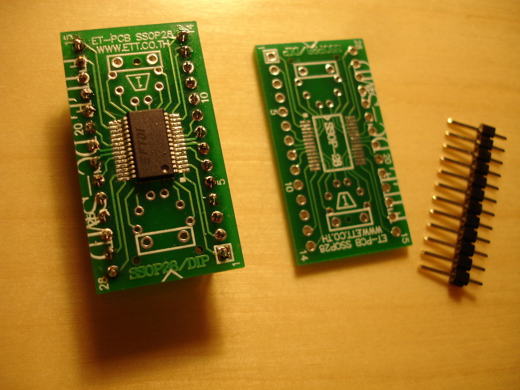
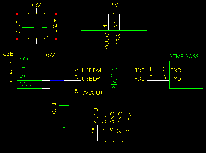
How about using the USB directly. This can be done. I chose the FTDI's FT232R chipset. It provides an UART interface to the MCU just as the MAX232 and on the computer side it looks like a serial port as well. This can be changed though by programming the vendor ID-s. FTDI offers free code libraries that can be used to interface with the system directly without the terminal interface.
For an amateur the chip might look intimidating though - it comes in the SSOP28 packaging. I ended up buying an adaptor board and soldering the FTDI chip onto it. The soldering was easier than I expected, I just pressed the hot iron against the chip's legs and they sunk into the adaptor contacts that melted slightly.

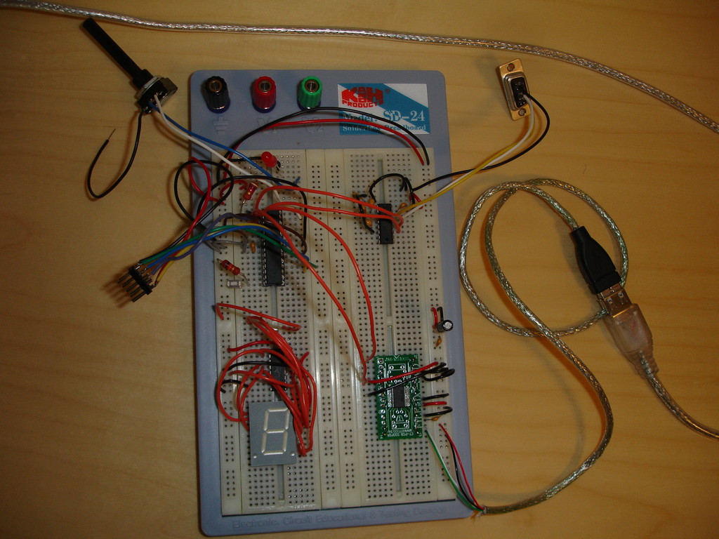
I went with the absolute minimum schematic and also powered the MCU from the USB - no batteries required here. This is not conforming to the USB requirements though - there is supposed to be a ferrite bead between the USB Vcc and the circuit to prevent noise from going up the USB bus. Read the FTDI's doc for a more specific example. Also in case a computer is turned off the circuit is allowed to draw very little current from the USB port - the mechanism for that is lacking from this circuit.
I cut open a USB cable and inside it found four wires - RED for VCC, BLACK for GND, WHITE for D- and GREEN for D+.
After I plugged the USB cable into the computer this is what I saw at dmesg:
usb 3-2: new full speed USB device using uhci_hcd and address 3
usb 3-2: new device found, idVendor=0403, idProduct=6001
usb 3-2: new device strings: Mfr=1, Product=2, SerialNumber=3
usb 3-2: Product: FT232R USB UART
usb 3-2: Manufacturer: FTDI
usb 3-2: SerialNumber: A4004Uiz
usb 3-2: configuration #1 chosen from 1 choice
drivers/usb/serial/usb-serial.c: USB Serial support registered for \
  FTDI USB Serial Device
ftdi_sio 3-2:1.0: FTDI USB Serial Device converter detected
drivers/usb/serial/ftdi_sio.c: Detected FT232BM
usb 3-2: FTDI USB Serial Device converter now attached to ttyUSB1
usbcore: registered new driver ftdi_sio
drivers/usb/serial/ftdi_sio.c: v1.4.3:USB FTDI Serial Converters Driver
Everything worked perfectly and just as with the RS232 adaptor cable.
|