Previously I've had fun building geiger counters. I decided to take this up a notch and get a bit more serious. This page is about my efforts building scintillation based radiation detectors. If all things go well, I'll end up with a gamma spectrometer, lucas cell, scintillation counters, etc :)
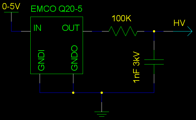
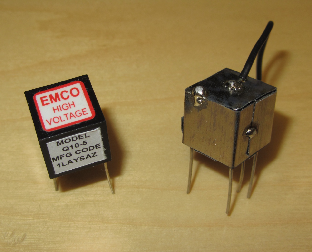
As scintillation detectors use more current, higher voltage and require a more stable voltage source, I went the easy way. Found some surplus EMCO Q-series DC to HV converters on eBay. These are very small and compact proportional voltage generators - so useful for portable/small applications. Their output is proportional to the input voltage. Still the specified noise is quite high so I added an RC low-pass filter to the end:
As the scintillation detector's own resistance is ~10-15MOhm, the 100K resistor won't affect the current and applied voltage too adversely.
Warning. This here is a high voltage source. In my adventures I managed to electrocute myself (the energy from the Q20 isn't enough to kill a person, unless one has a poor heart; but it was quite a jolt nonetheless so I felt like an idiot in the end;). Not nice. What's worse, by my careless activity I burned out one of the two channels of my o-scope. Ouch. So it is easy to ruin expensive equipment (this one was a USB-based o-scope, computer thankfully survived).
As I hooked up this circuit I was astounded by horrible noise. It was everywhere, it was huge, and nothing I did seemed to help. I finally realized that the noise came into the o-scope even as I was waving the probe (not connected) over the circuit. The EMCO part was leaking heavy RF waves. As I had recently aquired some mu-metal (for shielding Photomultipliers (PMT-s), probably more about this later), I just cut a few strips of that and clad the EMCO part, also grounding it. The EMCO cube now looks like a knight in armor. And noise problem solved :)
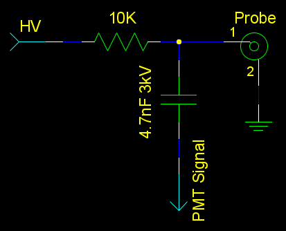
I got a used NaI(Tl) based detector through the GCE list. Label on it says "Alpha Spectra Inc.; Scintillation Detectors; 3I3X12/.75B". It has only one coaxial cable coming out of it. How does one go about coupling it into the circuit to get a meaningful signal? As it has a PMT in it that "connects" in case of a scintillation event (light), one just has to detect the voltage drop - this can be done by using a small 10K resistor in series with the probe:
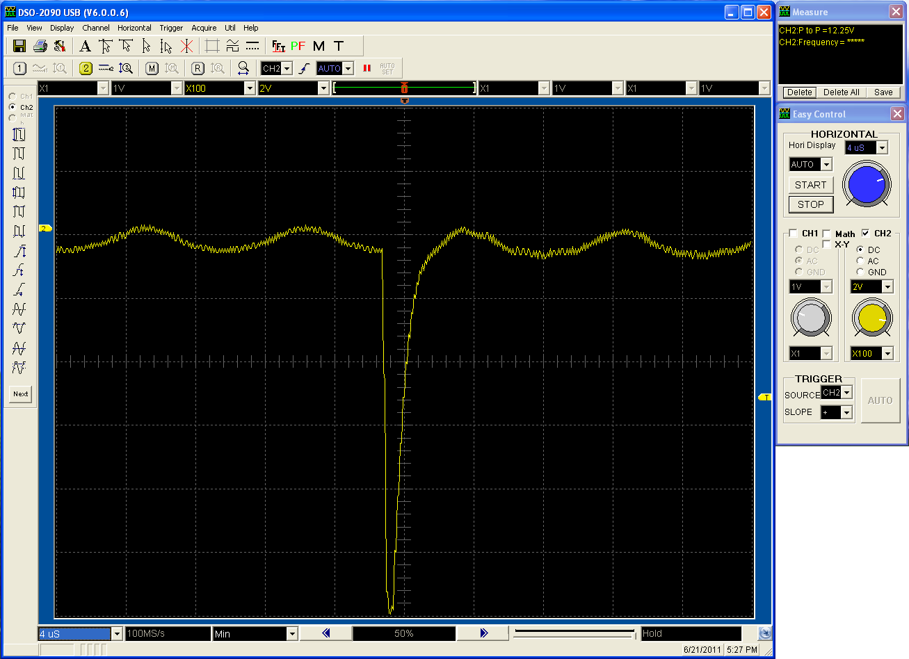
The HV cap isolates the signal. On the o-scope the scintillation event looks something like this (note: this is before I added the RC low-pass filter to the power source so you can see its noise here):
As you can see the signal is downwards and lasts about 2 microseconds. It's a negative pulse. In my measurements its amplitude seemed to be several volts (on the picture here the signal is bleeding into the super-high-impedance probe and so is distoring the reading). How to process it?
The simplest thing to do with the scintillation events is to count them. For that
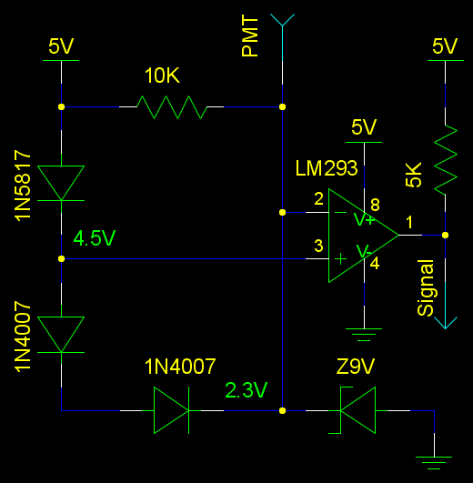
one would need a good signal to feed into a MCU. Or a sound generator. As all I have now is a negative voltage pulse, I need to process it to make it edible for a microcontroller/logic. Here's my solution
for such a circuit:
The previous circuit I had here had some problems. Notably the bias for voltage drops relied on
the opamp input bias current, the effective voltage drops were too small (<0.1V) due to the the
use of improper schottky diodes. Slept two days on it and realized it wasn't a good solution.
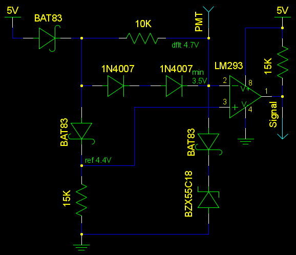
This one I tryed to make as safe and as foolproof as possible. I use diodes to make sure that current only
flows in the proper directions, to prevent noise from leaking into the supply. We use small currents and
the Schottky diode BAT83 offers a voltage drop of about 0.3V. So the PMT pin sees Vcc-0.3=4.7V.
The comparator compares this against the reference 4.4V - once voltage drops below it, we have a scintillation
event. So there is a 0.3V noise discriminator.
The two 1N4007 diodes (voltage drop ~0.6V at our currents) bypass the resistor and don't allow for the voltage
at the PMT pin to fall below Vcc-0.3-2*0.6=3.5V. To prevent against overvoltage, an 18V Zener diode is used. This one
should be of higher value (but below 30V) to prevent excessive leakage. So the opamp is completely protected
from over and under-voltage.
LM293 can sink current but as a source we only have the pull-up resistor. Good enough for logic but
not really for sourcing current or directly driving anything. For that a unity gain buffer should be added.
I've used here a 5V power source, but the circuit should work well in the range 3V-12V without any problem.
Also as the opamp is protected this circuit should take quite a bit of abuse and I hope works with
a wide range of signals.
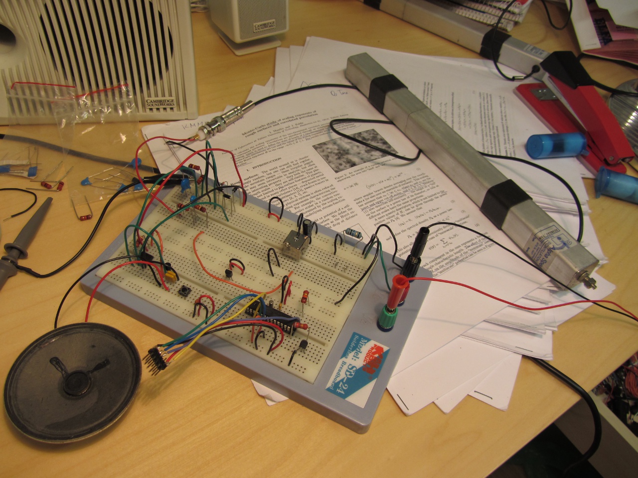
Here's my setup so far with an ad-hoc clicker circuit:
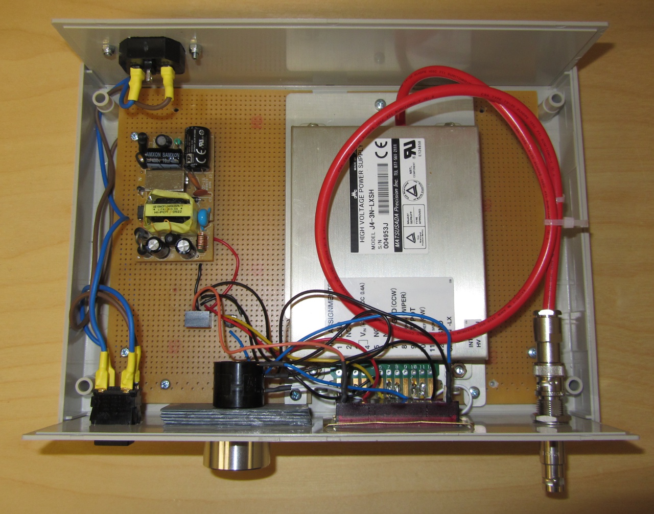
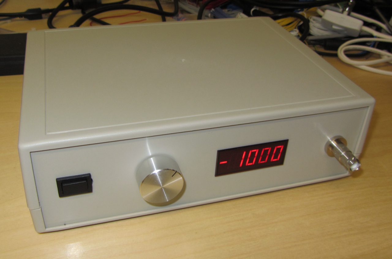
I found a "sold as new" (but received as used) cheap eBay Matsusada's 3kV J4-3N-LXSH extremely stable (less than 3mV peak-to-peak ripple) power supply. Decided to put it into a nice box with display, voltage dial and power switch. And an SHV connector. Ultimately a very expensive choice, but looks nice. Seems to work too. I don't get more than 2.3kV out of it. Probably because I went to the low end of the allowed 24-30V power supply (I got a 24V one, so I guess need to replace it to get higher voltages).
While one can tap the PMT signal from the ground level with a negative power supply, its use is complicated as the PMT should be wrapped in high kV negative voltage shell. I need a positive box like this too. eBay's runnin' dry at the moment :(