I realized I have no practical experience with working with electronics.
Except perhaps with higher end embedded systems (I've worked with arm9
development boards). But I have no clue how to organize resistors,
transistors, etc. to build a working circuit. This here is my first
project to teach myself.
The aim is to create a simple digital timer+alarm. It will enable the BUZZER every N minutes until the reset button is pressed, after RESET is pressed it waits another N minutes and restarts the BUZZER. If RESET is not pressed within 10 minutes after starting the BUZZER it is silenced. After turning on the device the N is by default 10. N can be changed using the UP or DOWN buttons from 1 to 99. The LED will by default display the time remaining until the alarm (in minutes or for the last minute in seconds); when UP or DOWN is pressed it will display blinking N for 5 seconds. During the buzzer the LED will display the time since the last reset (again blinking).
R0..R15 have limitations with some bit operations and assignments with constants
3 16-bit register-pairs that can be used as pointers (pointer-registers):
X - R26:R27, XL=R26, XH=R27, so 16 bit vaule is R27<<8+R26
Y - R28:R29, YL=R28, YH=R29
Z - R30:R31, ZL=R30, ZH=R31
One other 16-bit register pair R24:R25, does not work as a pointer but can be used as a counter.
Program memory (flash) can only be read using Z and R0 through the special LPM command, only up to 32kb
Pointer registers allow incrementala and decremental load and store
One can add/substract constants (0..63) to/from the 4 register pairs
Ports can be read/written using IN/OUT
Port ID-s are same across AVR chips
Specific bits on ports can be read/manipulated only on ports 0..0x20
Ports are also mapped into memory after registers (at address 0x20 and on, so addr=0x20+portid)
Y and Z pointers also allow read/store using offsets
integrated stack through the port pair SPH,SPL for addressing. PUSH, POP, stack grows down.
Functions using stack: RCALL, RET
Watchdog reset, has to be enabled, have to call WDR to avoid reset
At address 0 are all the interrupt vectors, vector 0 being the program start. That is addresses where to jump. The vectors are specific to different AVR chips.
Interrupt handlers need to reenable interrupts at the end by calling either SEI or RETI
Conditional jump is limited by +64/-64
Relative jump is limited by +2047/-2048
USART port. USART can be used to communicate between processors, into RS232 using logic2rs232 chips (say MAX232).
AVR USART can also be used as a data bus between multiple processors
One chip may have multiple USART ports
Timers/counters, two or three usually
PCINT interrupts, external input interrupts, can be on every IO PIN, notify about changes in input pins (edge trigger)
INT0, INT1, INT3, limited number, external input interrupts with more sophisticated control: falling edge, raising edge, low level, and also edge trigger.
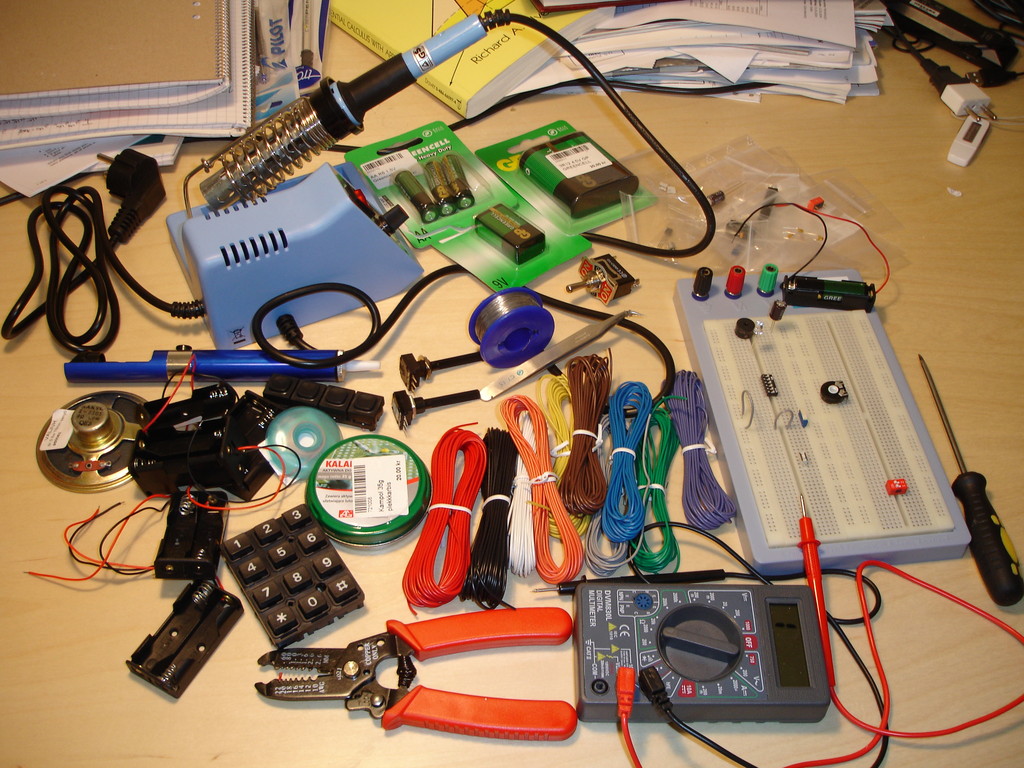
My new soldering station and lots of other stuff I need and don't need.
I still don't have the main CPU or the universal programming station.
But the buzzer buzzes and the LEDs light up.
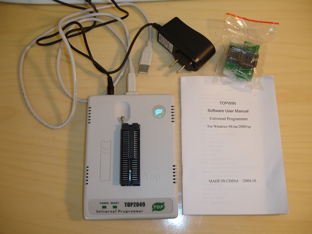
This is the TOP2049 universal programmer ordered over eBay from China. I run it on top of
Windows XP running in VirtualBox emulator under a Linux host.
Pulling a chip out from the circuit board every time for programming is troublesome. It takes time and puts stress on the parts. Also in some cases it is just impossible (for example when the chip is soldered onto the PCB). Also to shorten development time it would be cool to program the chip on the fly with least effort possible.
This can be done. Atmel has a special programming adapter for its AVR chips called the AVR STK500mkII. It costs around $25 off eBay. This also works with Linux and a program called avrdude. Avrdude can be integrated with the make system so one can compile, program and test the system on the fly in the good old UNIX CLI development environment. This is the best possible solution.
Or approaching this from another angle: once you build your device. Then you discover a bug in the microcontroller software or you want to make an improvement. How do you go upgrading the firmware? There are three possible ways:
You pry out the chip, insert it into a programmer and program it. Then you reinsert the chip into the device. This is the hardest and the most complicated process. Using a socket for your chip makes this easier.
You design a simple ICSP/similar socket into your device. You attach a cable and program it using the STK500 mkII. No special code or parts are needed in your design, just the socket and some wiring, everything required is already built into the AVR chips. This is what I do here. Of course you need the STK500 programmer box and that puts this solution out from the general consumer league. Still for example when a general consumer device is recalled for warranty reasons, then this is the most likely solution used by the manufacturer to fix it.
You build a special USB interface into your device design and write custom PC software so that the device can be upgraded using a simple general purpose computer and a USB cable. Even some moms can accomplish this.
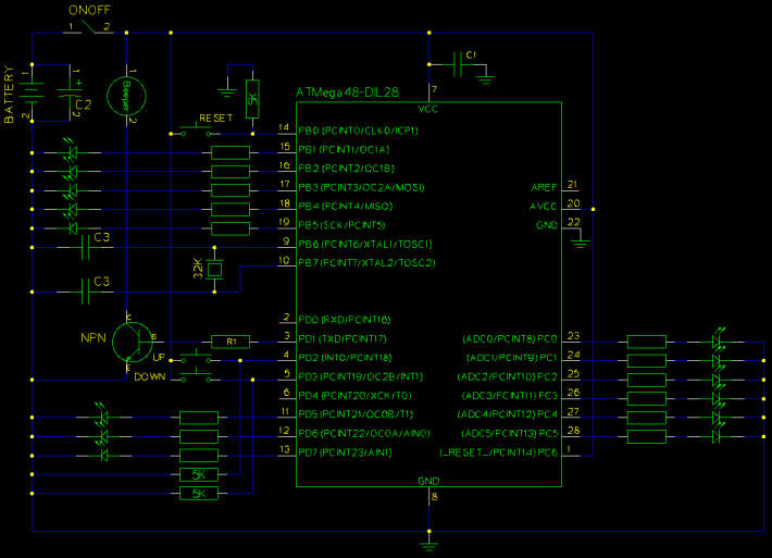
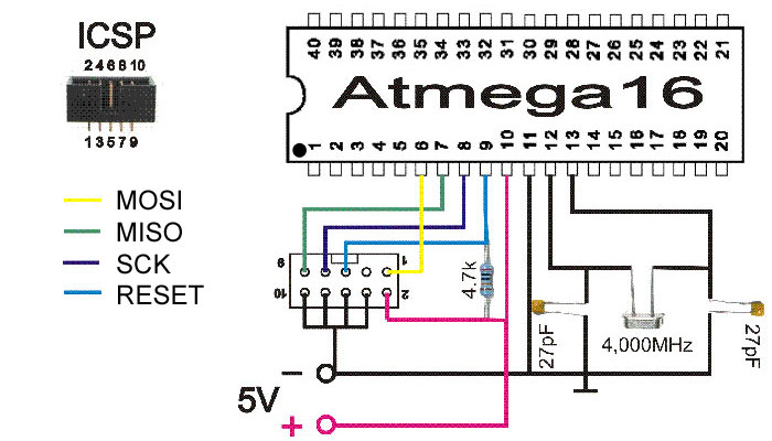
This here shows the wiring (stole this picture off an eBay's seller page). This schematic is for the ATMEGA16 and so has an external resonator/crystal in it. The ATMEGA168 I use does not require it. Note the 4.7K resistor - when the programmer activates it grounds the !RESET pin and the resistor insures that no short happens. In-system programming can be probably done on a "hot" device during development - that is even when it has all the other functions/pins attached to it. Programming will just reset the microcontroller.
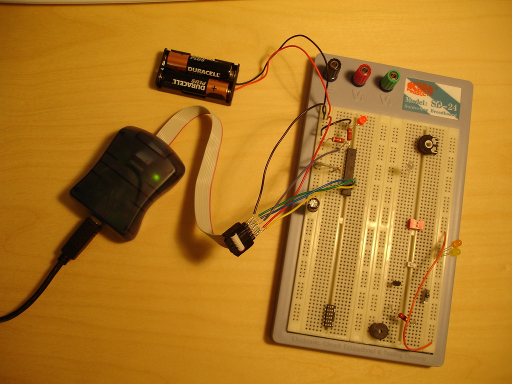
This picture shows my setup to test it out:
Once I pluged in the programmer this is what the Linux kernel reported:
usb 3-1: new full speed USB device using uhci_hcd and address 2
usb 3-1: new device found, idVendor=067b, idProduct=2303
usb 3-1: new device strings: Mfr=1, Product=2, SerialNumber=0
usb 3-1: Product: USB-Serial Controller
usb 3-1: Manufacturer: Prolific Technology Inc.
usb 3-1: configuration #1 chosen from 1 choice
usbcore: registered new driver usbserial
drivers/usb/serial/usb-serial.c: USB Serial support registered for generic
usbcore: registered new driver usbserial_generic
drivers/usb/serial/usb-serial.c: USB Serial Driver core
drivers/usb/serial/usb-serial.c: USB Serial support registered for pl2303
pl2303 3-1:1.0: pl2303 converter detected
usb 3-1: pl2303 converter now attached to ttyUSB0
usbcore: registered new driver pl2303
drivers/usb/serial/pl2303.c: Prolific PL2303 USB to serial adaptor driver
Programming on first try failed and I had to change the clock value:
% avrdude -c avrispv2 -p m168 -P /dev/ttyUSB0 -F -u -t

avrdude: AVR device initialized and ready to accept instructions

Reading | ################################################## | 100% 0.02s

avrdude: Device signature = 0xff00c0
avrdude: Expected signature for ATMEGA168 is 1E 94 06
avrdude: current erase-rewrite cycle count is 196608 (if being tracked)
avrdude> sck 1
>>> sck 1
avrdude: stk500v2_set_sck_period(): p = 1.0 us too small, using 1.1 us
avrdude> quit
>>> quit

avrdude done.  Thank you.

%
After that I reprogrammed the flash like this:
% avrdude -c avrispv2 -p m168 -P /dev/ttyUSB0 -U flash:w:hello.hex

avrdude: AVR device initialized and ready to accept instructions

Reading | ################################################## | 100% 0.02s

avrdude: Device signature = 0x1e9406
avrdude: NOTE: FLASH memory has been specified, an erase cycle will be performed
To disable this feature, specify the -D option.
avrdude: erasing chip
avrdude: reading input file "hello.hex"
avrdude: input file hello.hex auto detected as Intel Hex
avrdude: writing flash (146 bytes):

Writing | ################################################## | 100% 0.06s

avrdude: 146 bytes of flash written
avrdude: verifying flash memory against hello.hex:
avrdude: load data flash data from input file hello.hex:
avrdude: input file hello.hex auto detected as Intel Hex
avrdude: input file hello.hex contains 146 bytes
avrdude: reading on-chip flash data:

Reading | ################################################## | 100% 0.04s

avrdude: verifying ...
avrdude: 146 bytes of flash verified

avrdude: safemode: Fuses OK

avrdude done.  Thank you.

%
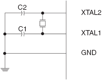
In our application we measure time. The internal builtin resonator in our ATMEGA168 is not very precise (may be some 10% off specified frequency). There's a possibility to use an external crystal resonator - a clock resonator at the standard 32768 Hz frequency. This will provide us with accurate timekeeping. Another advantage of this design is that we get reduced power consumption and so longer battery life.
The crystal resonator takes up two pins - XTAL1 and XTAL2 (PB6 and PB7). The crystal will even work without the capacitors present but the capacitors should make it more accurate. Both caps should be at around 15pF value (depending on the crystal specification).
To enable the external resonator the low fuse byte must be reprogrammed:
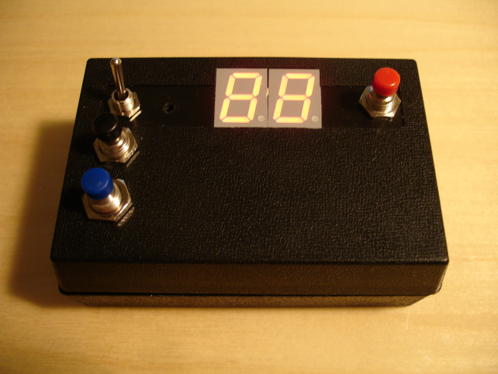
I'm so far with this project now that it's time to build the hardware. For that I need a plastic box with a PCB, some switches and wiring. So what I did was to take a very sharp knife and carve holes into the plastic box. The end result is following:
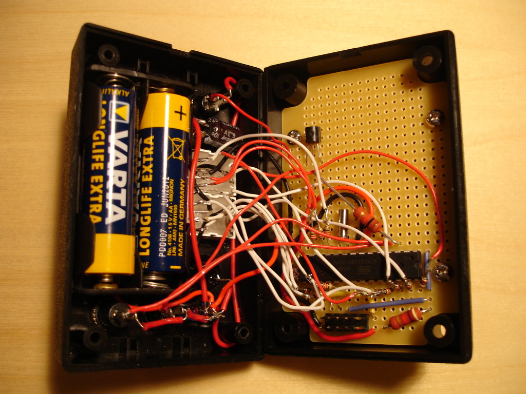
The on-off switch is on the top left, 3 push buttons (red being the reset) and the two LED displays. I'm not going to use the period led for now. The little hole between the leds and the on-off switch is for the piezo buzzer. I've started to use a different piezo buzzer that does not require inbuilt circuitry. It's attached on the other side with a bit of superglue. Lets look at the insides:
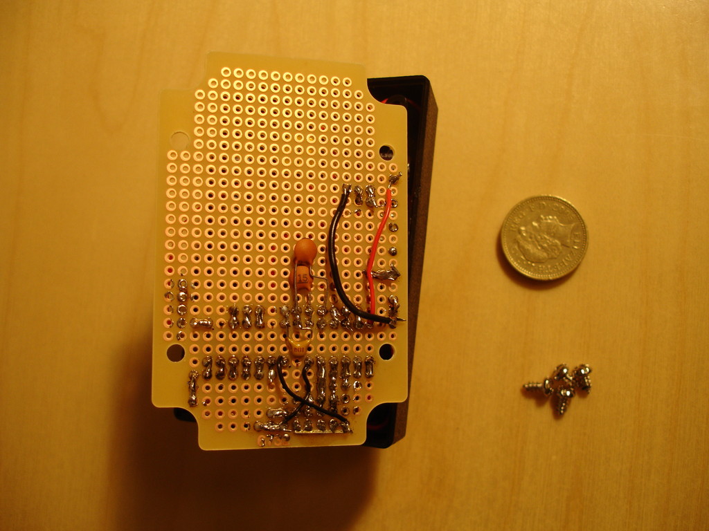
On the left you can see a battery holder (again attached with superglue). The box is closed using 4 screws so when it's time to replace the battery - the screws have to be undone. Next to the battery holder are the leds (white boxes) and above the leds is the big power capacitor. On the right side under the chip you can see the in-system serial programming interface socket - this makes it handy to finalize the firmware. The silver cylinder above the chip is the frequency crystal and on top left is the transistor used to drive the piezo.
I can't say I'm too proud of these solders. These are pretty much the first ones of my life. Here you can see the VCC-GND stability capacitor and the two crystal capacitors. I also put a few wires on this side - not a great practice but I am space constrained with this small box. Now it is time to build the proper firmware.
First I should get out of my way that I had forgoten to add pull-down resistors
for my input buttons. Well I did not forget but I did not realize at the start that something like that was necessary ;).
So I added three 5K resistors for each of the three buttons.
I made some improvements to the software: bounce removal and input repeating (if you press a key for more than 300ms, it starts repeating the key 10 times a second or so). Bounce is what happens when a button makes imperfect contact - the electrical circuit is actually closed and opened several times within a few milliseconds timespan due to mechanical issues. From human interface standpoint it should be counted as a single keypress though - and that's the problem to solve. Input repeating allows us to scroll up and down faster - one can just hold the button down and does not have to press it 99 times to move from 0 to 99.
I'm not really 100% happy with the software I wrote. I started using a central time concept - and in milliseconds. This forces one to use 32 bit integer arithmetic and divisions which results in a code size increase. Also the pin selection for LED-s was not perfect - I pretty much connected them randomly to available pins while soldering - did not follow any deeply premeditated plan. So this is not definitely production code, the binary size is is at 2672 bytes - a lot for this little thing. This can probably be coded to be one third of that or less.
The counter timeout value is stored in the EEPROM. So when the device is switched off it is preserved. It is updated only when there has been no changes for 4 seconds - that should help with the EEPROM write-cycles limit.
The counter timeout can be in minutes and also in seconds. When counting down at minutes we'll get a transitions from 1 minute to 59 seconds.
This is the source code: timer-0.4.tar.gz. Let me stress: this is my first electronics project and my first programming for a MCU.
 This here shows the wiring (stole this picture off an eBay's seller page). This schematic is for the ATMEGA16 and so has an external resonator/crystal in it. The ATMEGA168 I use does not require it. Note the 4.7K resistor - when the programmer activates it grounds the !RESET pin and the resistor insures that no short happens. In-system programming can be probably done on a "hot" device during development - that is even when it has all the other functions/pins attached to it. Programming will just reset the microcontroller.